

This guide applies to the Minister-Power MG Rover K Series Engines fitted with Roller Barrels.
| Tools required. 1. 1 x 6mm Spanner 2. 2 x 7mm Spanners 3. 1 x 2mm Allen key 4. 1 x 2.5mm Allen key 5. Digital Ohmmeter 6. Air flow meter (Not required for basic settings) |
Primary/Static Adjustments
Carryout these tests with engine off. Remove air filter or cowling from air filter system ensuring that all fixings are away from the engine and not stored in any filter or cowling parts. Replace your air filter at the earliest point after these procedures are complete. Idle (Static)
|
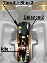
Fig. 1 |
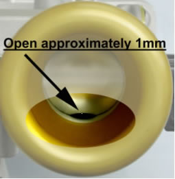
Full Throttle Stop (Rollers) Full Throttle (Cable) Full Throttle Stop (Pedal) |
Fig. 2 |
Dynamic Adjustments
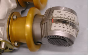
Dynamic Idle (Engine Running) Check that the throttle cable is free running, not caught on any linkage parts and that both rollers are at the idle position (Fig.1) Start engine and warm up to running temperature. Loosen locknut and adjust Idle Screw 1 (Fig.1) so that an engine idle speed of 1000rpm ± 50rpm and retighten locknut. Dynamic Balance (Engine RunningUsing an Air Flow Meter, (Fig.3) the flow rate through the rollers can be measured more accurately and will achieve a smoother running engine. Loosen locknut on Balance Screw 2 (Fig.1) and adjust so that the average readings from each roller on the flow meter are the same for each roller. Retighten locknut. Re set Dynamic idle as above. |
Fig. 3 |
Basic Potentiometer adjustments
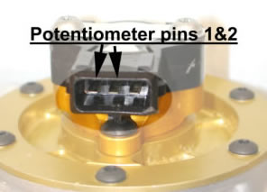
Fig. 4 |
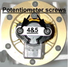
Fig. 5 |
Potentiometer Set-up (Basic) Turn Engine Off.
With an Ohmmeter set to 20K scale, connect the cables to pins 1 and 2 (Fig.4) A reading of 0.45 Ohms is desired with the rollers at idle. Minimal adjustment is made by loosening screws 4&5 (Fig.5) and turning the potentiometer. Retighten screws 4&5 This completes the Basic Roller Barrel Induction System set-up.
Computerised setting up of your engine can be arranged at the Minister-Power factory, for a nominal charge. Please call us on 01634 682577.